Monterey K104 restoration
This was the first photo I saw of the keyboard:
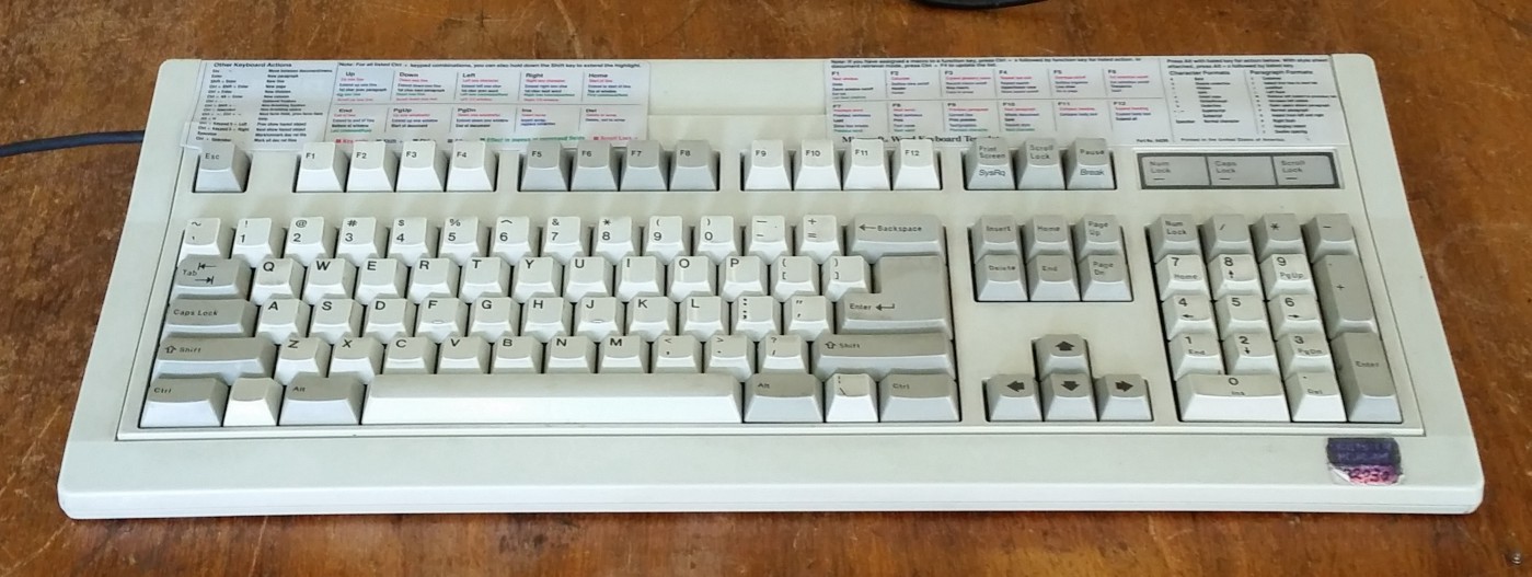
My first impression of this keyboard.
I received this photo from a local not-for-profit that takes donations of old PC hardware and builds computers for people who need them but can’t afford them. After deciding that I really wanted an IBM Model M keyboard (prized for its clicky buckling springs), I had been sending emails around to places that specialize in old hardware in the hopes of finding one. I sent an email to this company briefly outlining that I was looking to buy any old clicky keyboards they had, and this is what they sent back to me.
Keen eyed keyboard enthusiasts will notice that this in-fact isn’t a Model M, but I didn’t know this at the time. I made a post on Reddit asking for help identifying the keyboard, and a helpful user called /u/syn-ec-do-che was quite sure it was a Monterey K104. At this point I was a little disappointed that it wasn’t a Model M, but I went over to pick it up anyway. For $15 I figured it was a good deal, even if it wasn’t exactly what I was looking for. Little did I know what awaited me.
When I finally got it home and pulled the keycaps, I was greeted with something pretty wonderful. The keycaps are double-shot ABS, and it sports Alps blue SKCM switches, which are clicky and have an actuation force of about 70cN (a little less than Cherry Greens). What a find! Apparently this board has been spotted with a few other types of switches (including non-mechanical ones), but these blue Alps are some of the rarer switches. And rarity aside, I really like heavy clicky switches, so this was about as perfect an outcome as I could hope for.
Cleaning
The next step in getting this keyboard in working order was a thorough clean. Sadly I didn’t have the foresight to take photos pre-cleaning, but suffice to say this thing was filthy! It had a ‘University of Melbourne’ sticker on it, and evidently the student’s did not treat it well. The keycaps were filthy and below them was a disgusting amount of crumbs, hair and other detritus. But following the /r/mk keyboard cleaning guide it was shiny and clean in no time.
What particularly surprised me was the effectiveness of denture cleaning tabs for cleaning the keycaps. After half an hour soaking in the cleaning solution they came up brilliantly. I also removed that Microsoft word shortcuts cheat sheet (thankfully only secured with blu-tack), a strange metallic logo that seemed to be from some long defunct computer retailer and a few other stickers and bits of debris. Finally, I gave the outer case a good scrub with some soapy water and I vacuumed out the inside of the case, just to get it really sparkling.
What particularly surprised me was the effectiveness of denture cleaning tabs for cleaning the keycaps. After half an hour soaking in the cleaning solution they came up brilliantly. I also removed that Microsoft word shortcuts cheat sheet (thankfully only secured with blu-tack), a strange metallic logo that seemed to be from some long defunct computer retailer and a few other stickers and bits of debris. Finally, I gave the outer case a good scrub with some soapy water and I vacuumed out the inside of the case, just to get it really sparkling.
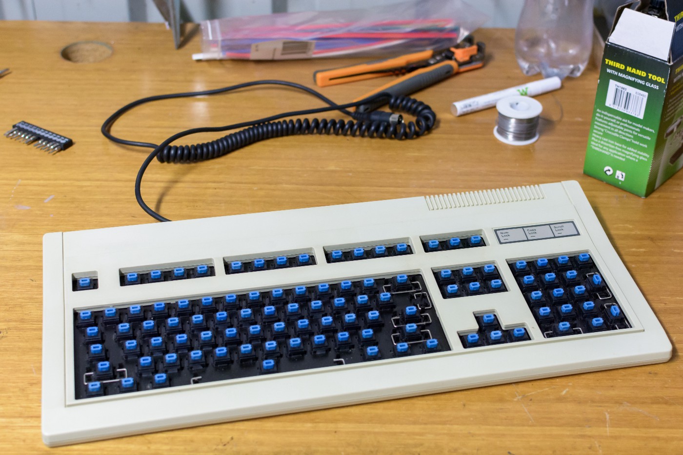
All cleaned up with keycaps pulled.
Cable coiling 101
As you can see in the above photo, the original cable that came with the keyboard was nicely coiled. Since I was aiming for a pretty faithful restoration, I also wanted a cable that was coiled.
One option would have been to do a very neat job of snipping the existing terminations off of the cable and re-terminating it male USB to male micro USB. However since I don’t have the crimping tools I decided against this. It also would have made the internal connection of the micro-controller a little more difficult because I would have had to de-solder the old wiring and solder some new ones. Not terribly frustrating, but I didn’t want to tempt fate with such old hardware.
The option I went with was to buy a new micro USB cable and do the coiling myself. The process of coiling cables is pretty easy — coil the cable around some cylindrical object of the right diameter, heat the cable, allow it to cool, and you’re done. You can see some photos of this process below.
For a first try I’d say I did an ok job, however this is one part of the project that I’m going to redo at some point. Here’s the issues I ran into:
The cable I bought wasn’t thick enough. Not only does this not match the original cable as I’d wanted, I think it also means the coiling looks different.
The coiling itself is a fair bit harder than it sounds. You really need to be extremely careful with making all of the coils under exactly the same tension. This is made even harder by the fact that you have to somehow secure the coiled cable to the mandrel you’re winding it around at both ends, while still maintaining tension. This is almost certainly a two person job; one to hold the tension and one to tape the cable to the mandrel.
I suspect you have to be pretty precise with the heating. Next time a consult of the literature on commercial coiling of cables and a thermometer will be in order.
The result of these difficulties has left me with a cable that is coiled, but not tightly like the original (or like other professional cable coilings I’ve seen), not very evenly in diameter, and that has spread quite a bit in the few weeks since I coiled it.
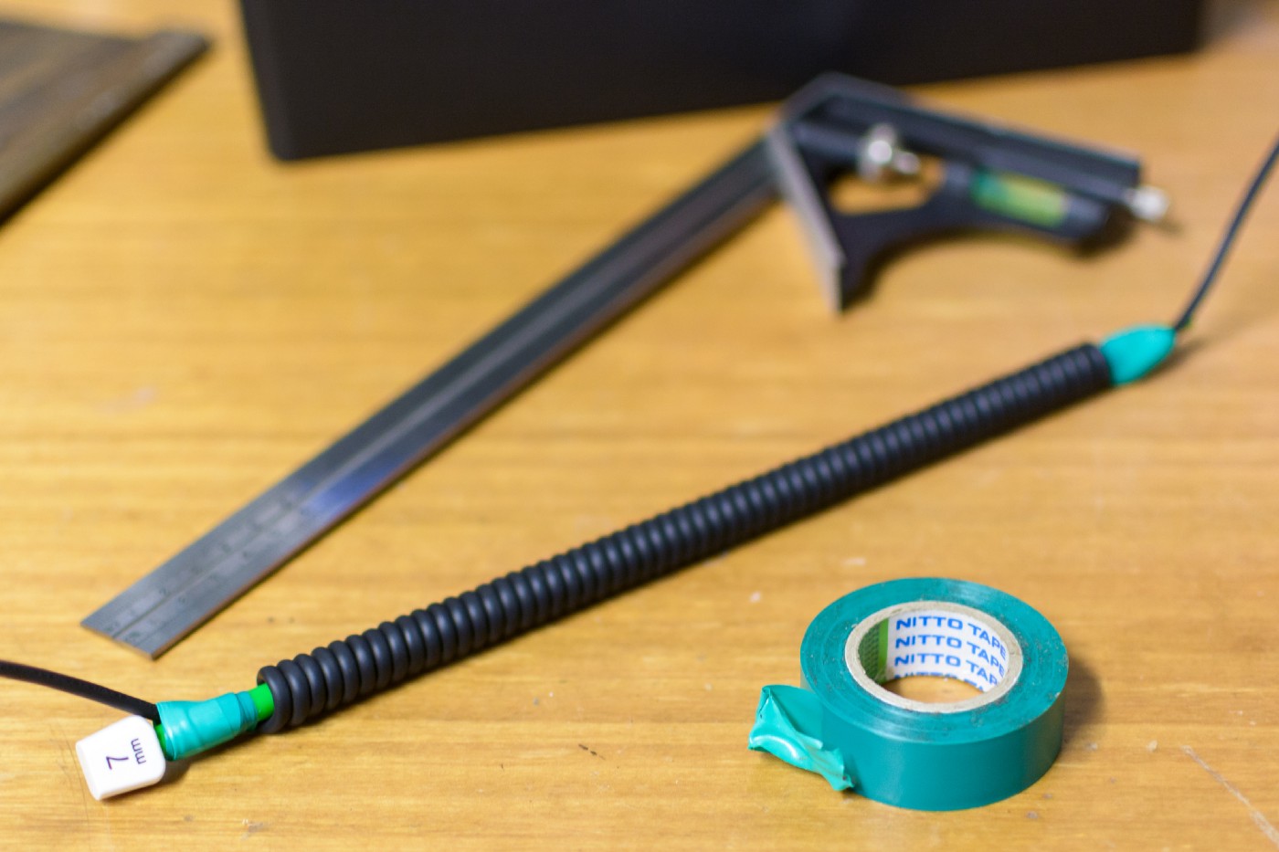
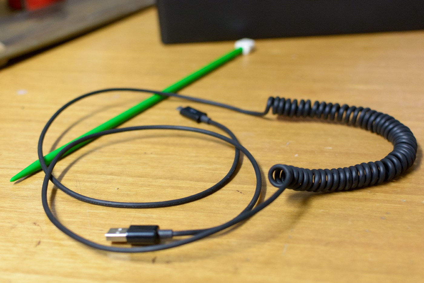
Cable coiled and ready to be heated.
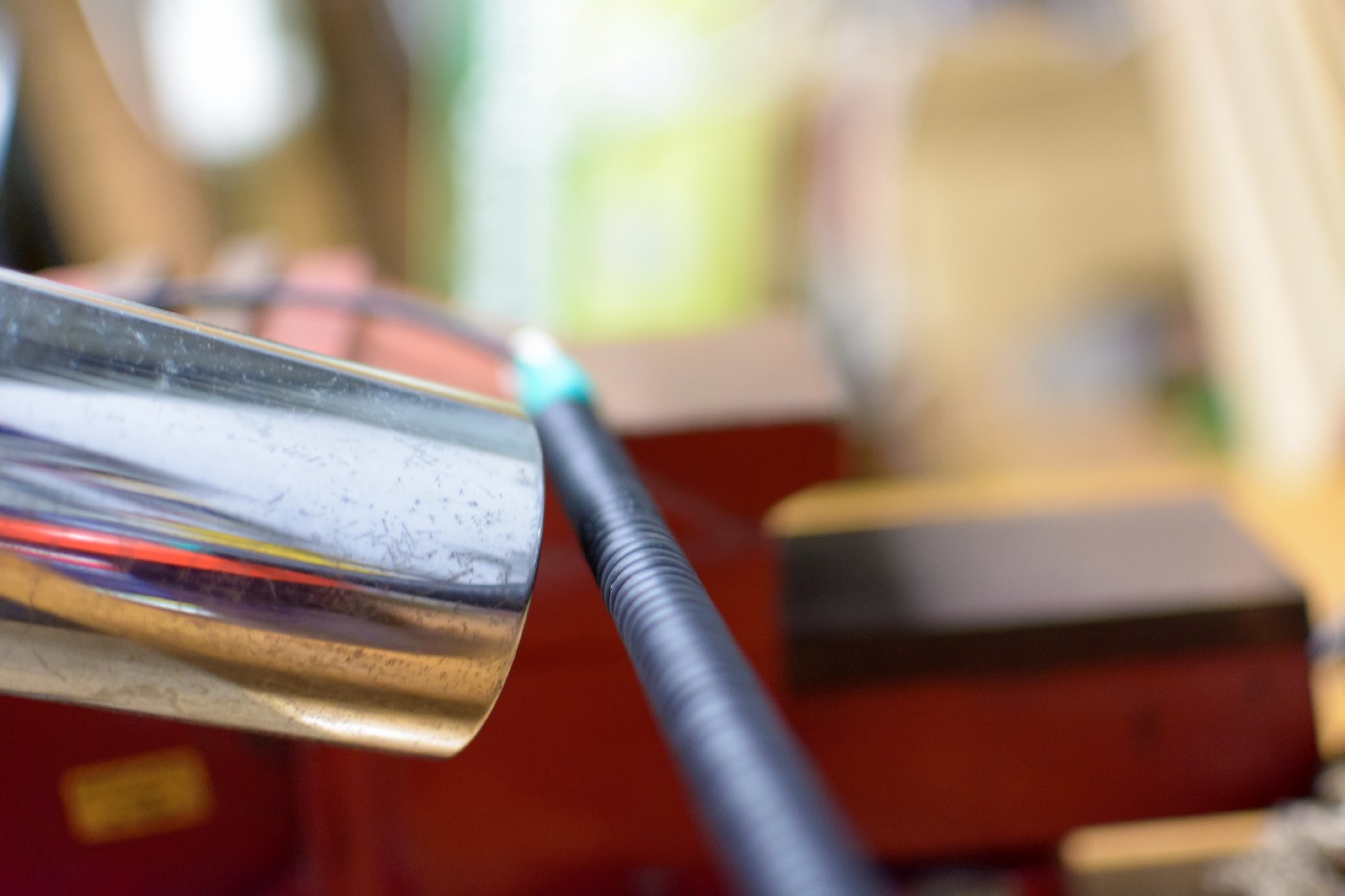
Heating with my trusty workshop hairdrier.
Removed from mandrel. Note the slightly uneven coiling.
Protocol conversion
The next step in getting this keyboard to a state where it was usable was to convert it to USB. This keyboard was manufactured in 1989, which predates the USB protocol by about seven years. As a consequence, this keyboard originally had a DIN connector and spoke either the AT or XT keyboard protocol (depending on the position of a switch on the back). Thankfully, converting old keyboards to USB is a solved problem.
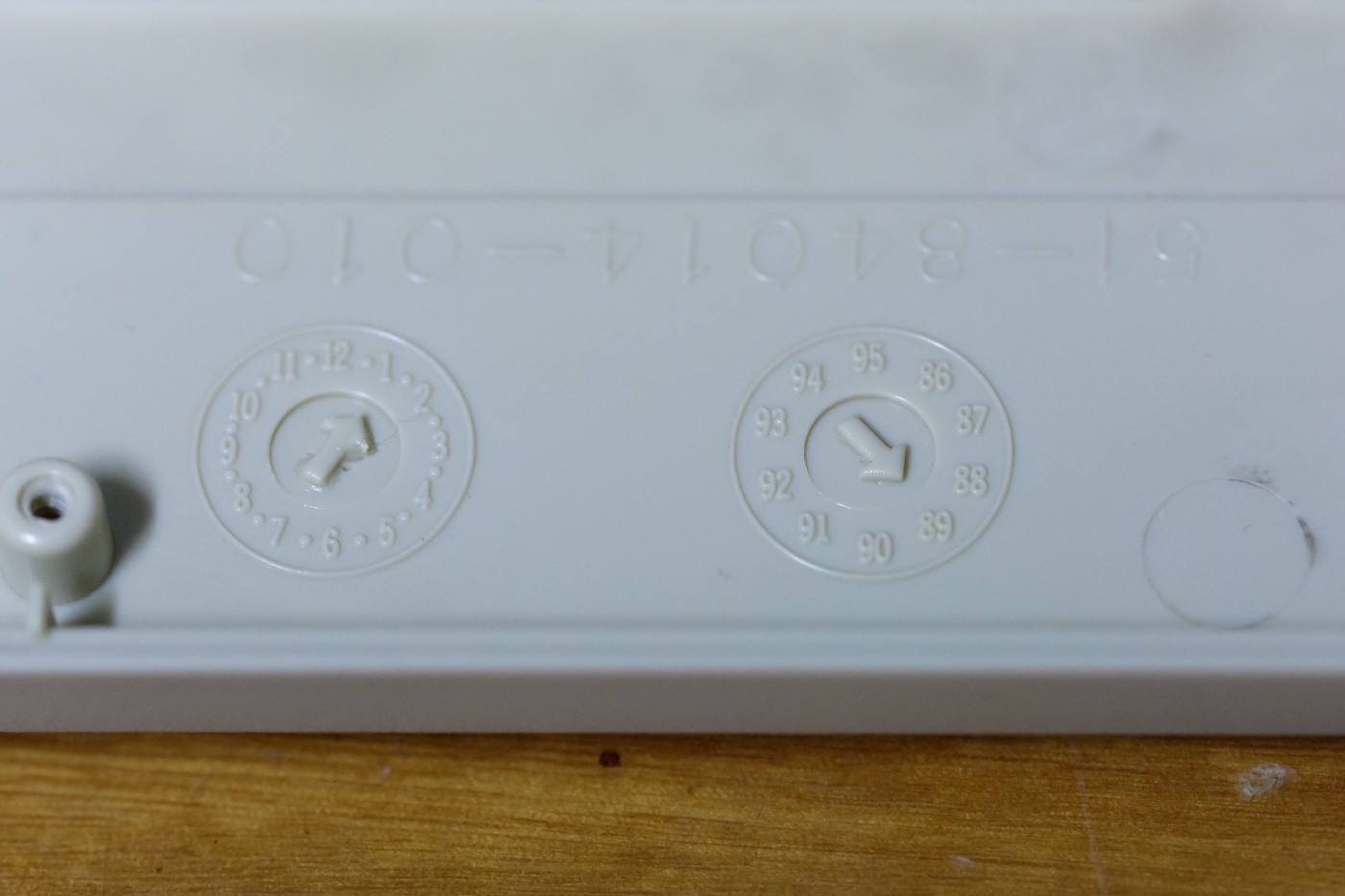
Manufactured January 1989.
I decided to make use of Soarer’s converter for this project. Soarer’s is a well known and well established set of software and firmware, and it’s pretty easy to get started with. In terms of hardware, you need a microcontroller breakout board that has a USB host controller on it, which allows the microcontroller to masquerade as an input device. Sadly this ruled out the many Arduino Nanos I bought a few months ago, however AliExpress has Pro Micro boards for very cheap.
Next step was to open up the case and see where everything was going to fit. Thankfully the following facts made fitting things really easy:
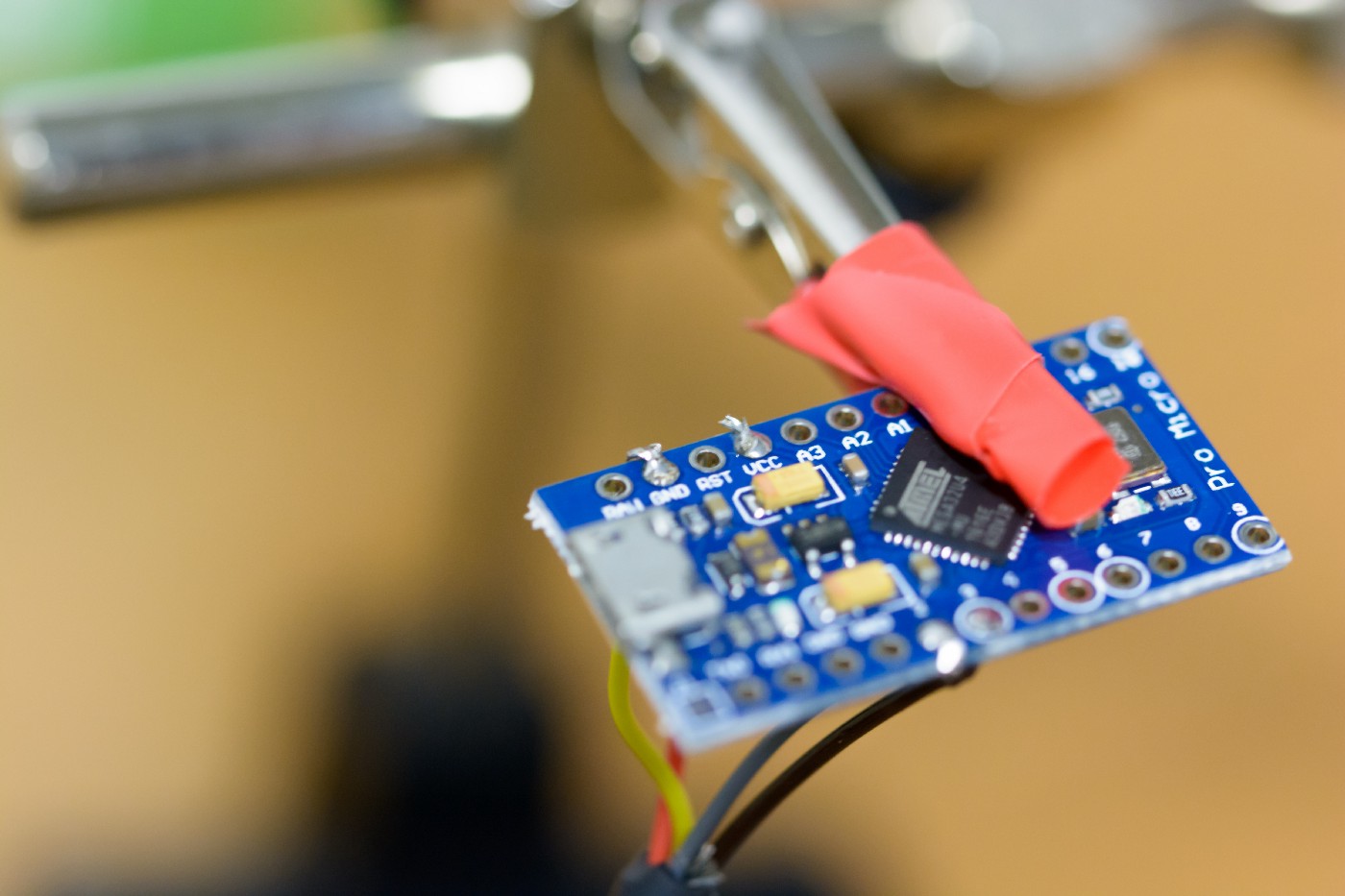
There was loads of room in the case to mount the microcontroller. I made the decision early on that I wanted the keyboard to look as similar as possible externally. Hence, I would need to mount the Pro Micro internally. This was easy because of all of the extra space inside.
A nice bit of cable management with multiple strain relief bits built into the case. Apparently the Pro Micro’s micro USB socket is notorious for becoming detached from the board. Thankfully this wouldn’t be an issue with the board’s little pegs that serve to hold the cable in place and relieve strain. And there were even multiple sets of these as you can see in some of the images, presumably for other versions of the board where the cable mounts to the mainboard in a different location.
The first item of business with this protocol conversion was to determine which wires corresponded to which pins on the DIN connector. This involved lopping off the connector and making use of my quite ancient multi-meter.
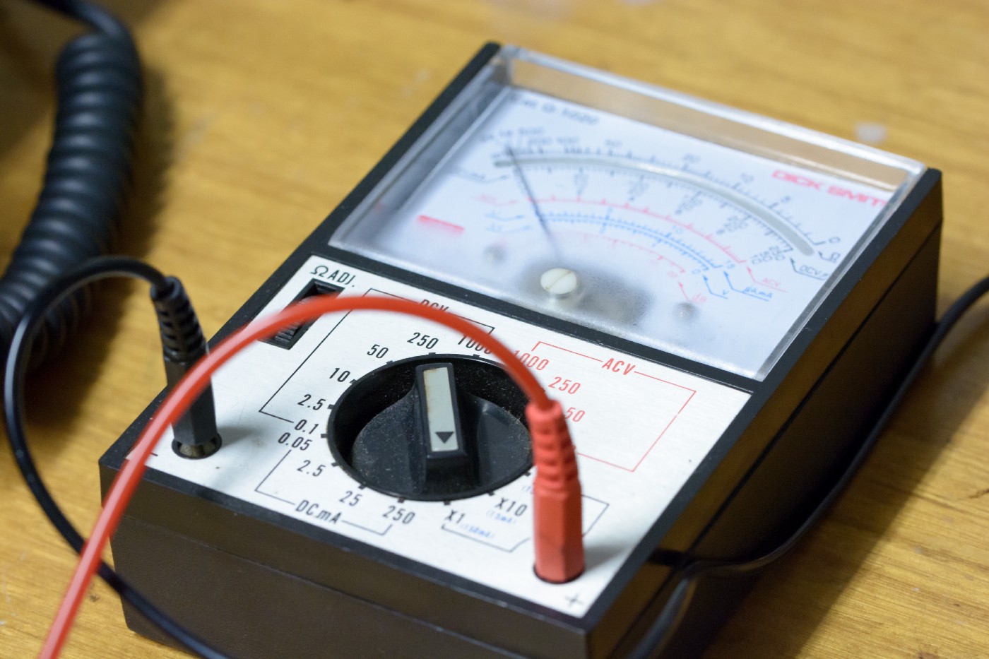
Ancient multi-meter. The box says ‘Dick Smith’ (now defunct).
I used the wiring guide shown below to match the pins from the DIN connector to their relevant signals. Almost all Soarer’s converter pinouts are shown using the Teensy, but thankfully I was able to find a deskauthority post which details the corresponding pins on a Pro Micro I was using.
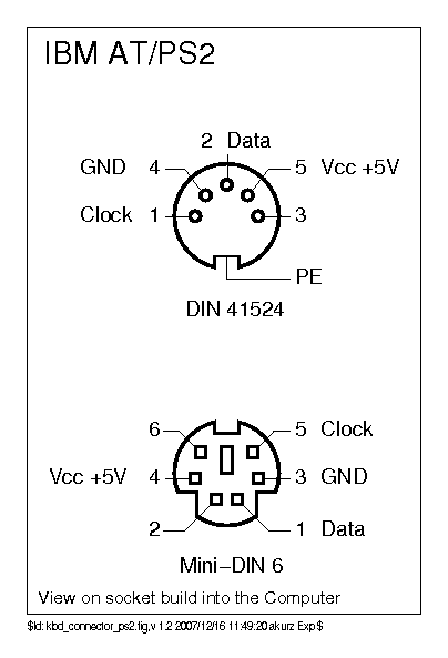
DIN connector AT wiring guide.
Once I had figured out which wires were which and where they were all going, it was time to strip them all and tin them. This isn’t going to be a tutorial on soldering, but generally when soldering you flow some solder onto the bare wire before attempting to solder it to anything. This leads to better joints, and with stranded wire (as was the case here) it also means you don’t get stray strands shorting out your work and ruining your day.
Another crucial element when soldering is making sure that you have decent mechanical connection before soldering. Otherwise you’re putting all of the stress on the solder and it’s likely to fail. To this effort I decided to twist the tinned wires into little hooks before attaching them to the Pro Micro.
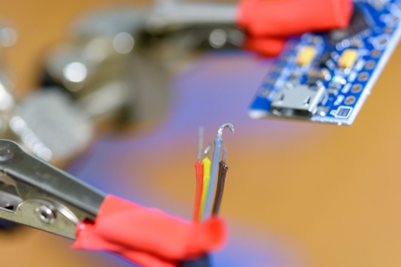
Tinned and hooked wires
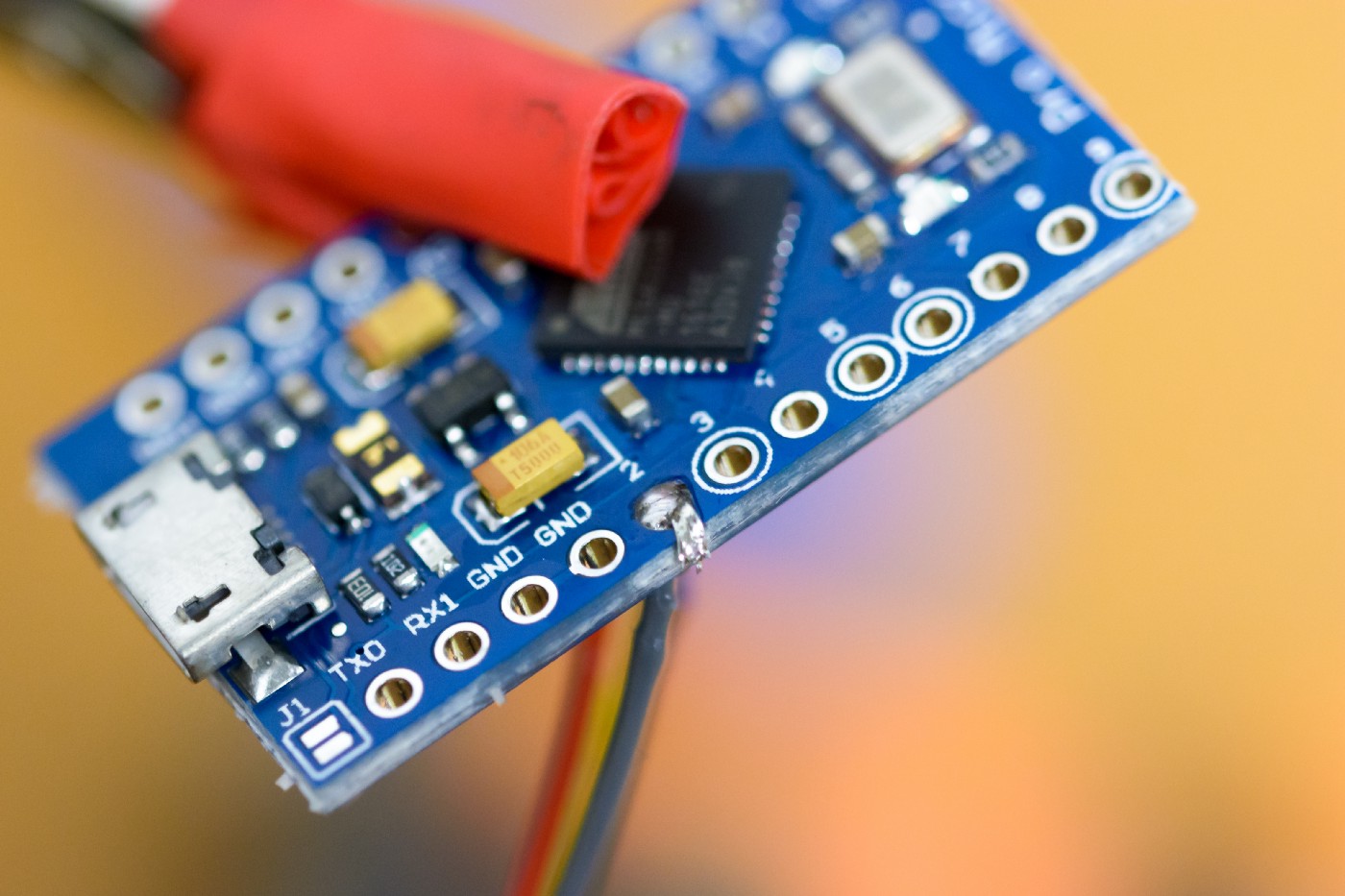
Next step was the soldering. It was pretty nerve-wracking, but ultimately I think I did a pretty neat and clean job.
One wire attached (I think this is the clock).
All the wires soldered on.
Now, a brief interlude on flashing Soarer’s firmware. I actually performed this step before I had soldered the Pro Micro to the keyboard, but this was mostly because I wanted to mess around with it late one night but I wasn’t ready to break out the soldering iron just yet. I’m not going to cover the specifics here because that’s well documented elsewhere, however I’ll talk briefly about some pitfalls I ran into:
Getting the Pro Micro into bootloader mode can be annoying. I believe the Teensy has a dedicated reset switch, but the Pro Micro (likely due to cheapness) does not. In order to emulate this feature on the Pro Micro, you need to short the GND and RST pins twice in quick succession. You’ll know you’ve done it right, because approximately 8 seconds later the LED on the Pro Micro will flash, which means it’s exited bootloader mode. You need to be in bootloader mode in order to write Soarer’s firmware to the Pro Micro.
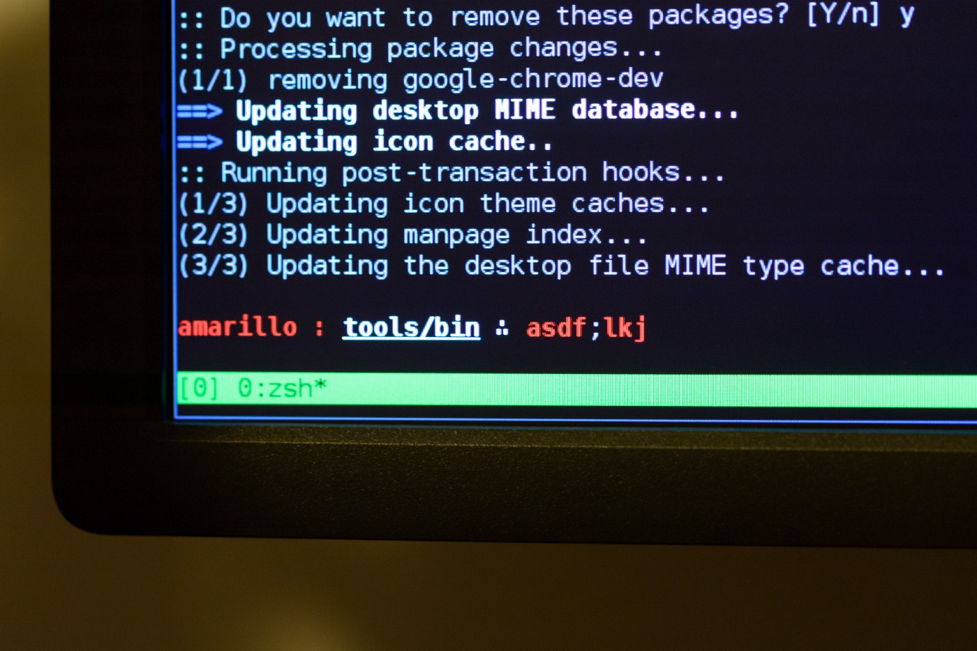
It’s almost not worth mentioning, but I didn’t have USB connectivity issues under Linux (specifically Arch Linux). As has been the case in the past, a reboot fixed things, but watch out for this because it’s incredibly frustrating. You plug the device in and out over and over, watching /dev/ for device changes and combing through dmesg logs, only to come up with nothing that will make the flashing succeed. Maddening!
Once the firmware is loaded onto the Pro Micro, it’s a simple enough task to load the desired key configuration file. I had to compile the tools that Soarer provided for this from source, but the makefiles are pretty straightforward. For some reason my compiler wasn’t using the c99 standard which caused some issues, but just be sure to either add this to the provided Makefiles as part of the CFLAGS variable and you should be ok.
My keyboard configuration file for this keyboard was extremely straightforward, because it has all of the keys you’d really ever want. I needed only three small bits of custom config (though you can go absolutely nuts using Soarer’s, including layers and complex key combos)
- I remapped Caps Lock to Control, because Caps Lock is stupid.
- Just in case I ever do actually need the Caps Lock function, I mapped Shift + Control to Caps Lock.
- I mapped the blank button on the bottom left of the keyboard to the windows/super key, because it’s not mapped to that by default (more on this pesky key later).
Next came the moment of truth. At this point I still didn’t actually know if the board even worked. I had guessed it would, simply because externally and internally it looked to be in very good condition. Thankfully when I plugged it in for the first time, the green num-lock light lit up, and I knew all this effort hadn’t been for nothing.
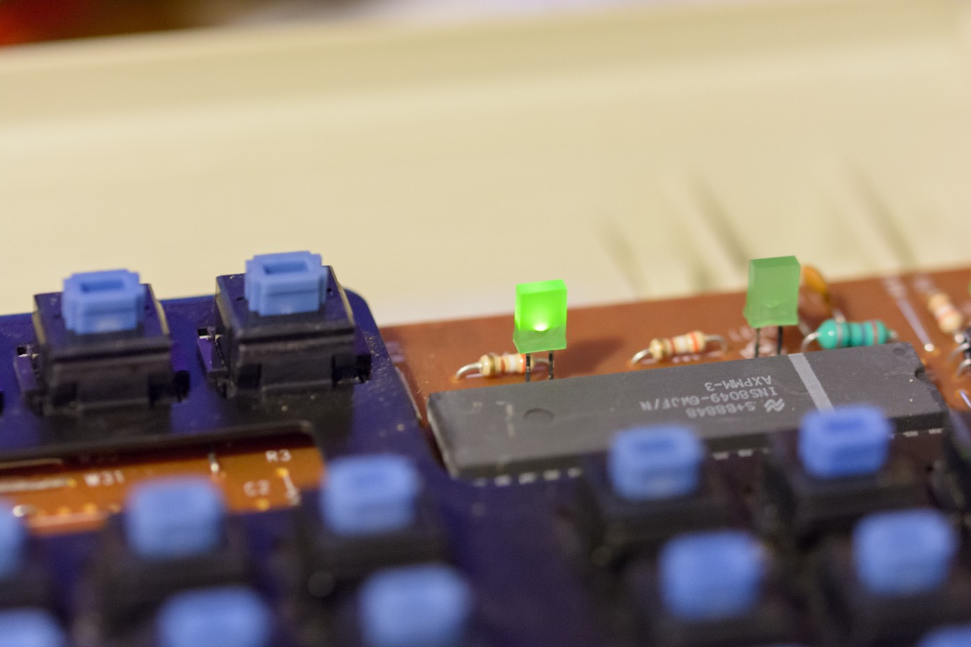
The first sign of life - a lit up num-lock light
The first key-presses of a revived K104
Success! The num-lock light turned on and at that point I was pretty confident that everything had gone to plan. The first order of business was to fire up a keyboard testing website and ensure that everything was working as intended. Much to my dismay, every key worked EXCEPT for the blank key in the bottom left.
Ordinarily this wouldn’t be a huge deal. However with no other location to put a super key, and with my very frequent use of the super key (it’s the main key used to perform actions within the Linux window manager I use, AwesomeWM), this was pretty devastating. I decided to investigate.
Thankfully for situations exactly like this one, Soarer has put debugging information into the data that the firmware sends to the computer. In order to sniff this debugging info, you need a program called hid_listen. Once you have this working, you can see the raw HID information that the keyboard is sending to the PC. When I ran hid_listen and pressed the non-working super key, I saw nothing. Absolutely nothing. This was interesting. The first thing I did was check the configuration file and fiddle with it to see if that was the issue. It wasn’t. Then I started googling. Thankfully I came across a forum post which makes just the barest mention of a key not working. Based on this I decided to do some investigating.
After studying the underside of the circuit board and investigating with the multi-meter, I eventually discovered that quite bizarrely, the windows key switch is not electrically connected to the board. Even more strangely, I suspect this was a deliberate act by the manufacturer and that the board was manufactured this way. As you’ll see in the image below, one of the terminals of the switch leads to a strange little clearing on the circuit board where there are two small blobs of solder. These were not electrically connected, but as soon as I put down a blob of solder to make this connection, the key immediately started working. Really bizarre that they would bother putting a key there, but then not connect it at all. I guess it could have been part of a re-usable design, so perhaps some variants of this keyboard do have this key connected. Regardless, I was just incredibly happy that the fix was so easy.
(As an aside, if this hadn’t worked, I would have simply wired the switch directly the to Pro Micro. Soarer’s converter apparently supports four additional input devices which can be used as modifiers. Suggestions include things like pedals or footswitches, but I can’t see any reason why you couldn’t wire a switch directly to one of the auxilliary inputs and remap it to the desired key in configuration. Thankfully I didn’t have to find out if this is easy or not.)
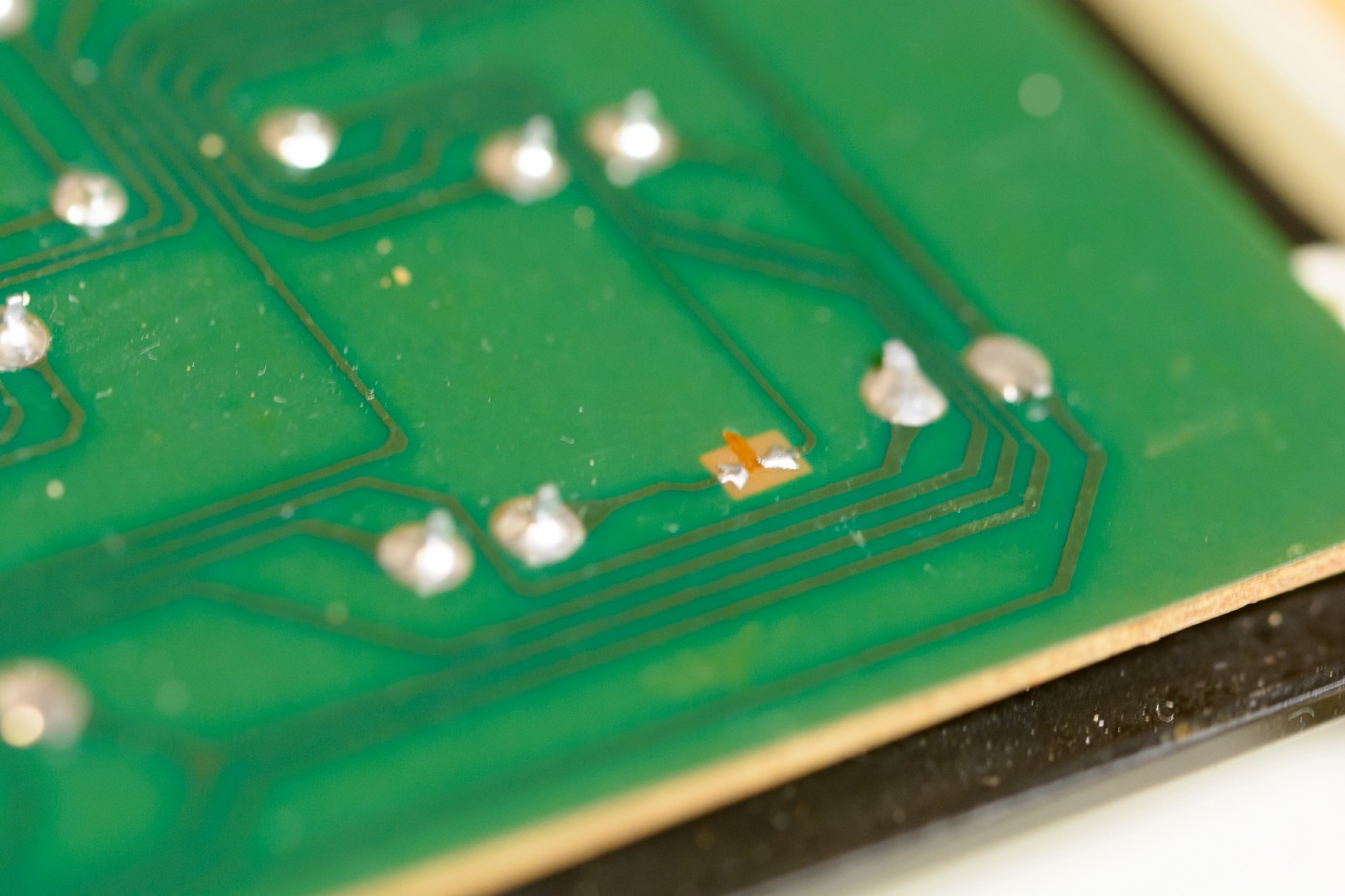
Un-bridged solder pad. Very strange.

Slightly ugly solder job to bridge the connection
Final thoughts
Overall, I was incredibly happy with how this project turned out.
I didn’t really show it in the images, but I’m very proud of the neat soldering and cable routing job I did, and I’m happy that I was able to troubleshoot the issues I had with the super key.
A few other bits and pieces that don’t really fit anywhere else:
- Annoyingly the Pro Micro has a red LED that is always on when the board has power. This was shining through between the F10 and F11 keys. A bit of electrical tape fixed that.
- Be careful when screwing the case closed when you having hanging stabilizers. I closed up the case for what I thought would be the last time, only to realize that a stabilizer on the enter key was caught underneath the case. Not a big deal, but annoying
- The cable coiling thing is really annoying. I could just get a custom cable made from the numerous companies that do them, but it seems like a waste for what is just a plain black cable. In a moment of impulsiveness I ordered some USB and some micro USB connectors from AliExpress for a few dollars, so I may try and make my own cable. Unfortunately, a thick, 5M, black micro USB cable doesn’t seem to exist on ebay. You can find thick, 5M, white micro USB cables. You can find thick, 3M, black micro USB cables. But no black 5M ones.
Something I’ve neglected to mention until now is the feel of this keyboard. I’ve been using it as my work keyboard for the past three weeks, and typing on it is an incredible feeling. It’s sharply clicky, has great resistance, and it sounds amazing. I think the sound is a combination of some resonance in the stabilizers on the larger keys, but possibly also resonance from the extra space inside the case and from the metal key plate. It’s really wonderful to type on, and I really hope there are no complaints from my coworkers (none so far thankfully).
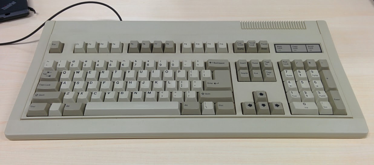
Keyboard on my desk at work.